Configuration Example for ECMP
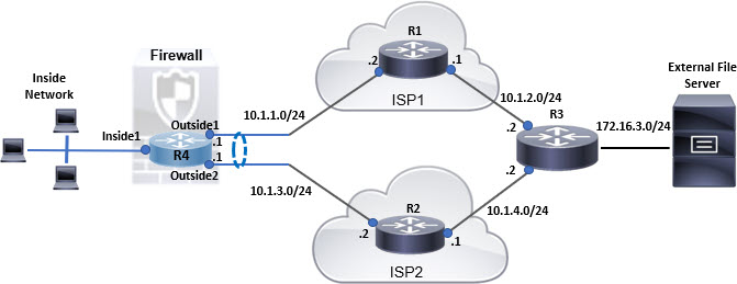
This example demonstrates how to use Firewall Management Center to configure ECMP zones on Firewall Threat Defense such that the traffic flowing through the device is handled efficiently. With ECMP configured, Firewall Threat Defense maintains the routing table per zone basis, and hence it makes it possible to re-route the packets in the best possible routes. Thus, ECMP supports asymmetric routing, load balancing, and handles lost traffic seamlessly. In this example, R4 records the two paths to reach the external file server.
Procedure
| 1 |
Create virtual router—R4 with Inside1, Outside1, and Outside2 interfaces: 
|
| 2 |
Create ECMP zones:
|
| 3 |
Create static routes for the zone interfaces:
Ensure to specify same metric, but different gateways for the static routes: 
|
| 4 |
Save and Deploy. |


The network packets to reach its destination, R3, follows R4>R1>R3 or R4>R2>R3, based on the ECMP algorithm. If R1>R3 route is lost, the traffic flows through R2 without any packet drops. Similarly, the response from R3 can be received by Outside2 though the packet was sent from Outside1. In addition, when the network traffic is heavy, R4 distributes them between the two routes and thus balances the load.